1.1 Tofu Hardness Analyzer
Project Context
Tofu Hardness Analyzer
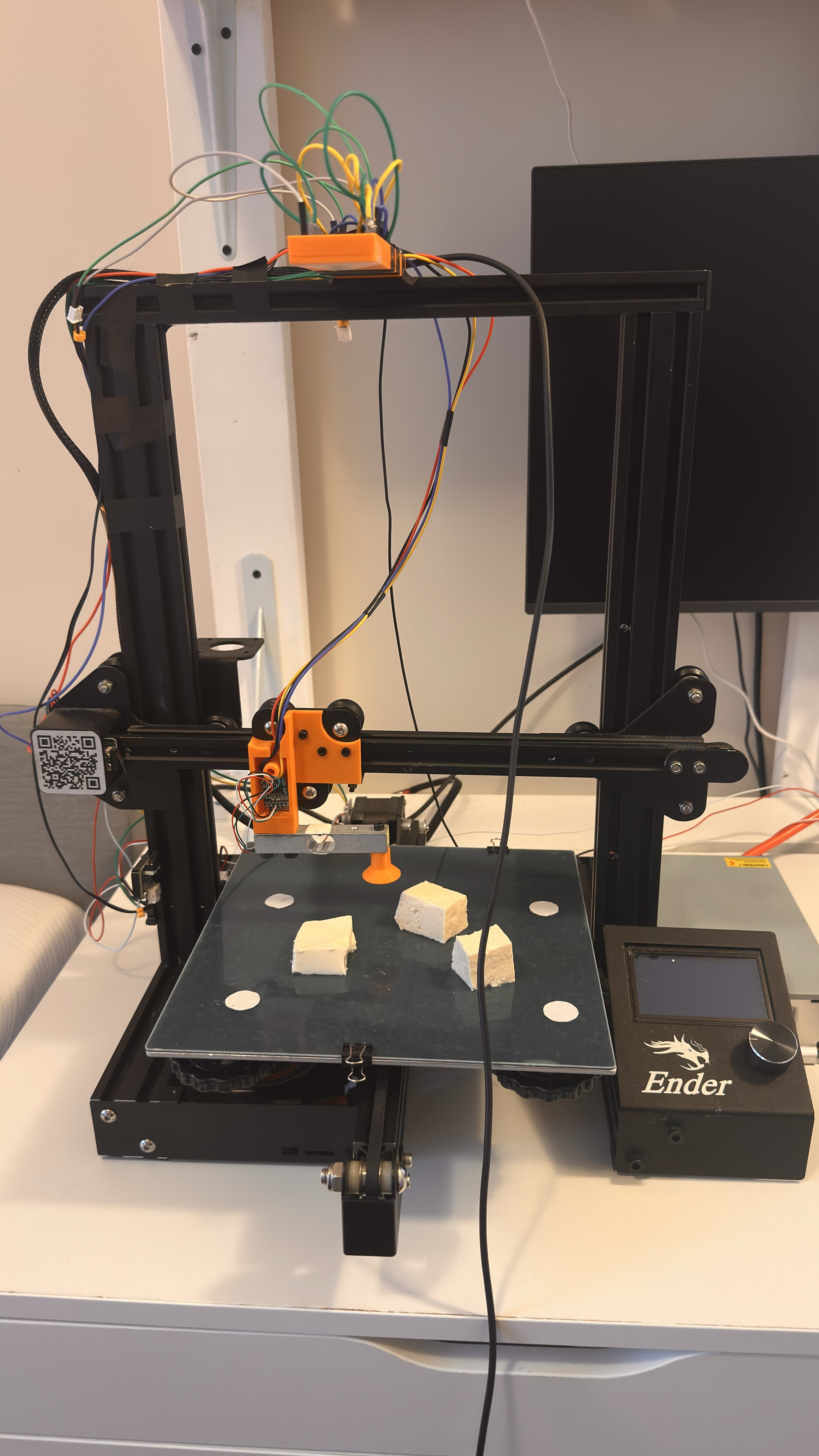
A desktop-scale hardness measurement device built from a salvaged 3D printer.
Overview
A desktop-scale measurement device that determines the hardness of test samples, built to showcase mechatronics skills and to learn image recognition. The machine identifies tofu pieces on its build plate using computer vision, then performs a compression test on each one to classify it as soft, firm, or extra firm.
At a glance
- Base
- Salvaged 3D printer
- Controller
- ESP32-S3 Nova Cam
- Motion
- 3× MKS42 closed-loop
- Sensing
- HX711 load cell
- Vision
- OpenCV on PC
- Metric
- Effective modulus (kPa)
- Output
- Soft · Firm · Extra firm
How It Started
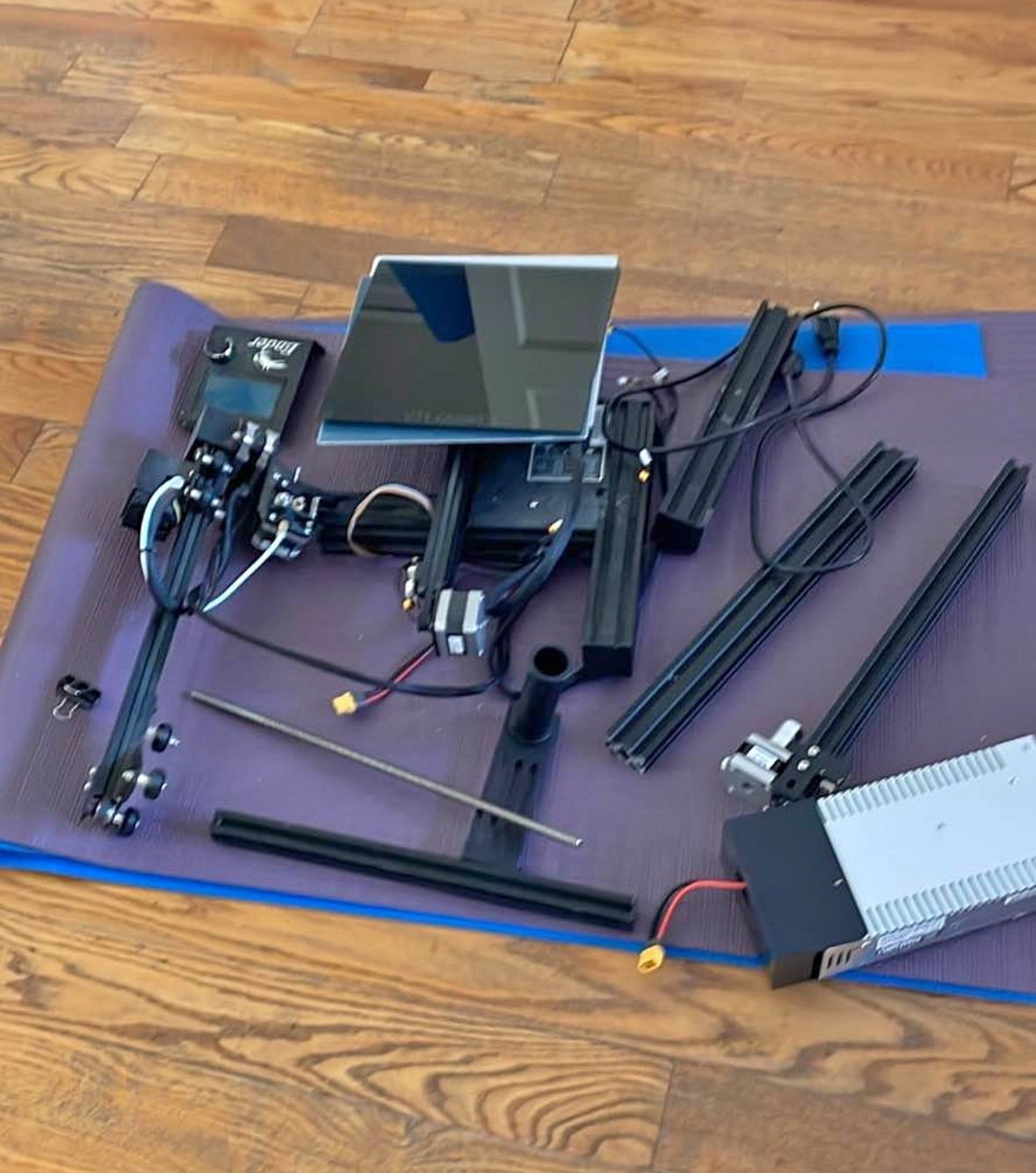
I bought a used 3D printer off Marketplace intending to harvest it for parts. After pulling the stepper motors and the motherboard, I decided it would be more interesting to turn it into something else instead.
At the time I was applying for a mechanical engineering position at a food startup, so I built a hardness analyzer for tofu. The goal was to take real measurements and determine whether a sample was soft, firm, or extra firm.
Hardware Decisions
Closed-loop stepper motors
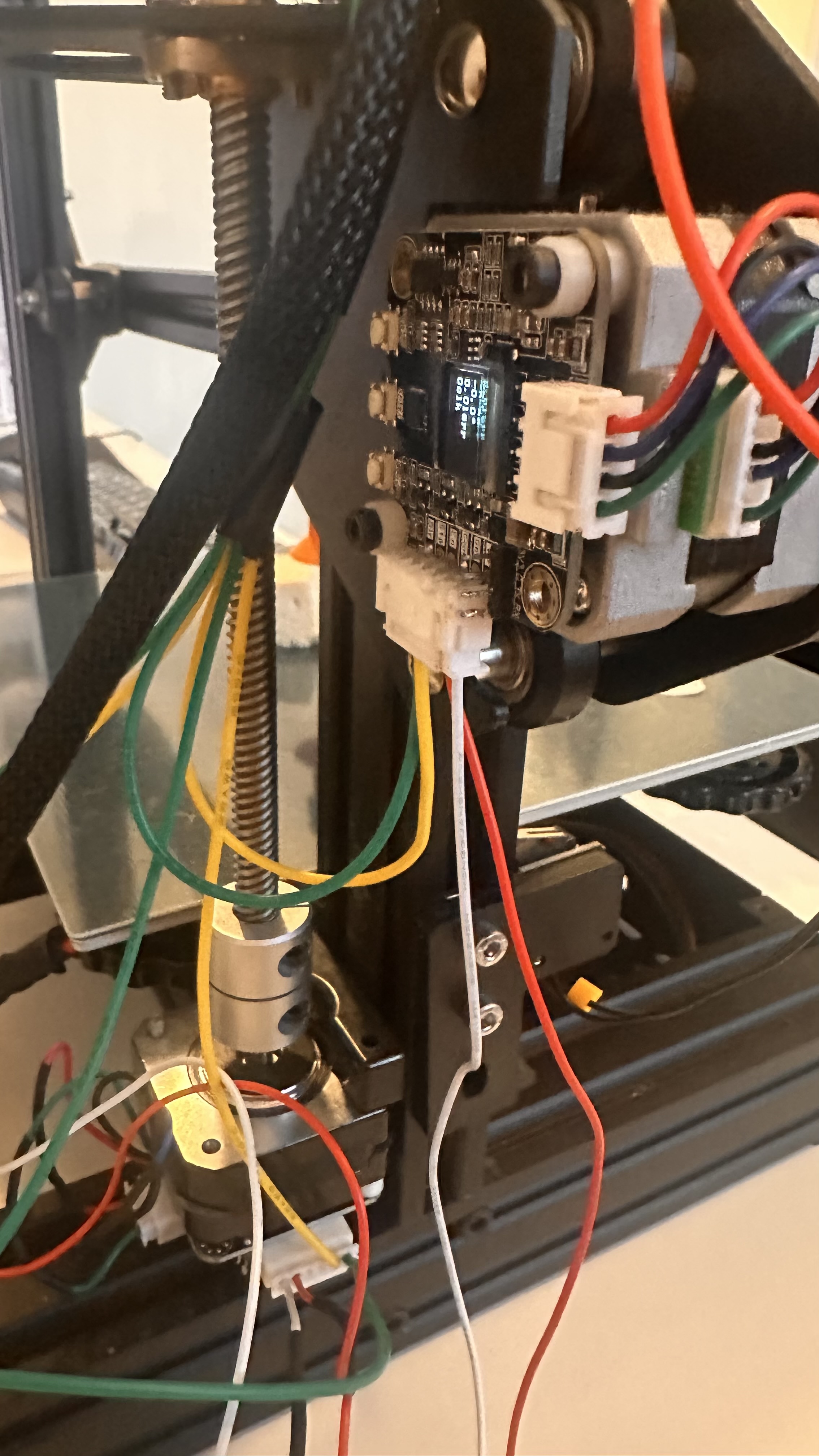
MKS42 servo
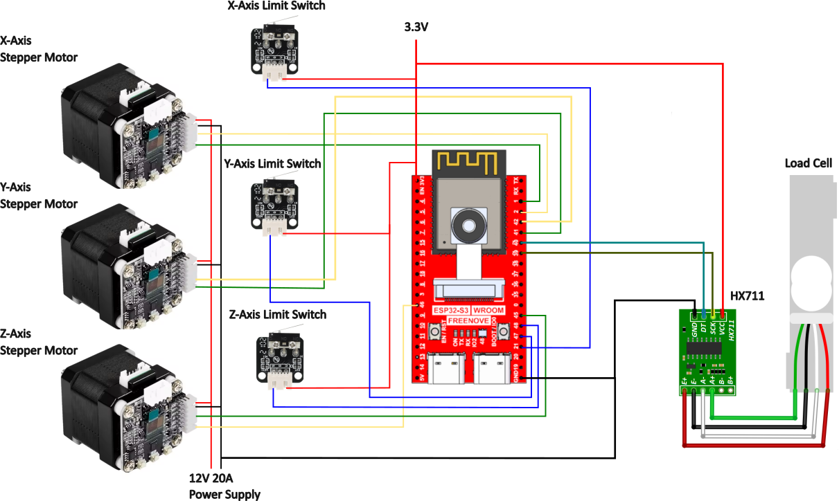
Each module integrates the driver and encoder directly onto the motor. This simplified wire management considerably and gave better positional precision than the open-loop drivers the printer shipped with.
Controller + camera
ESP32-S3 Nova Cam
Chosen for two reasons: enough RAM to handle image capture and buffering, and a built-in camera, which is one less subsystem to integrate.
Homing
3× limit switches
Kept the printer's three original limit switches to home all axes and establish a known origin on startup.
Force sensing
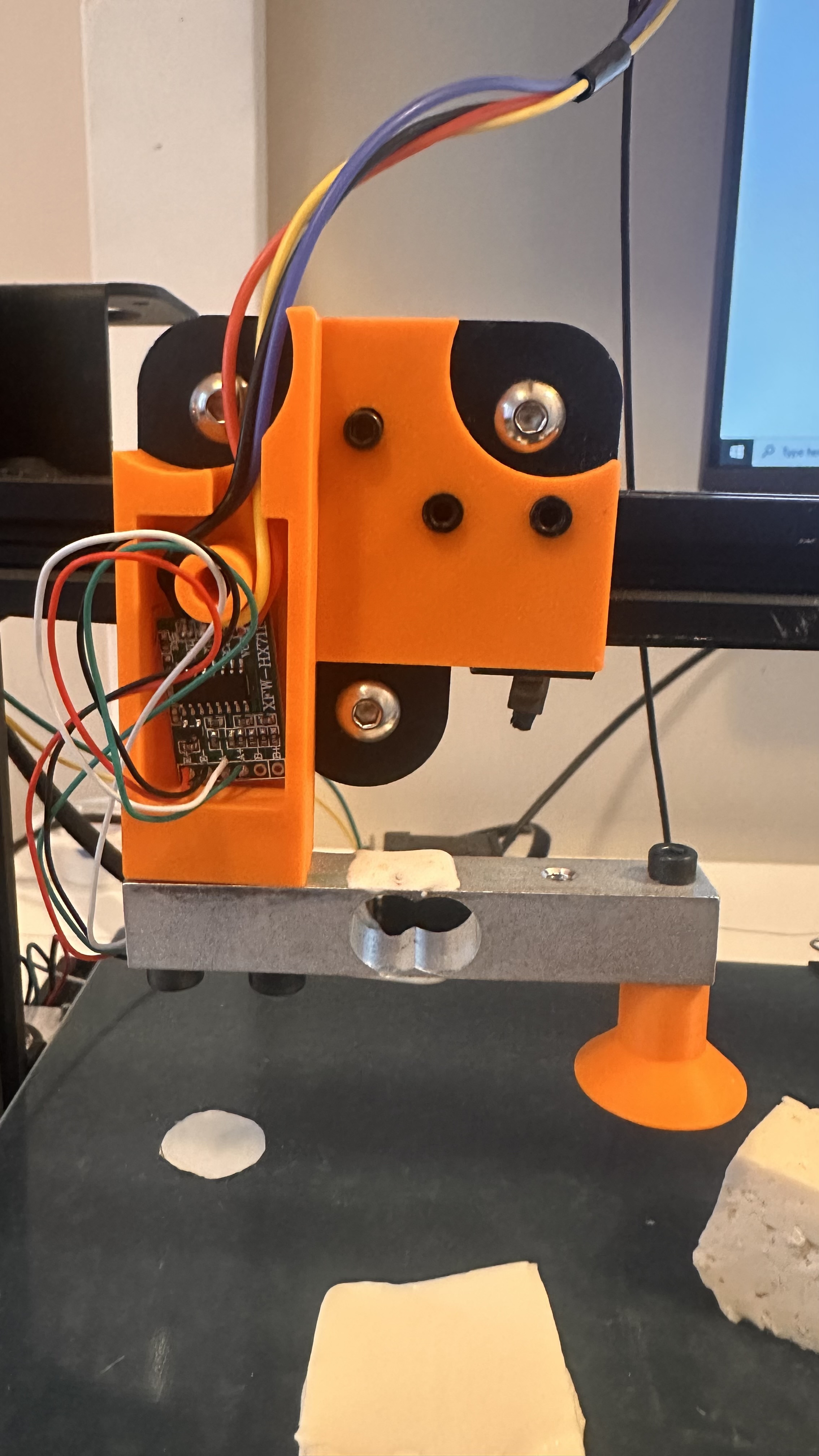
Custom HX711 load-cell mount
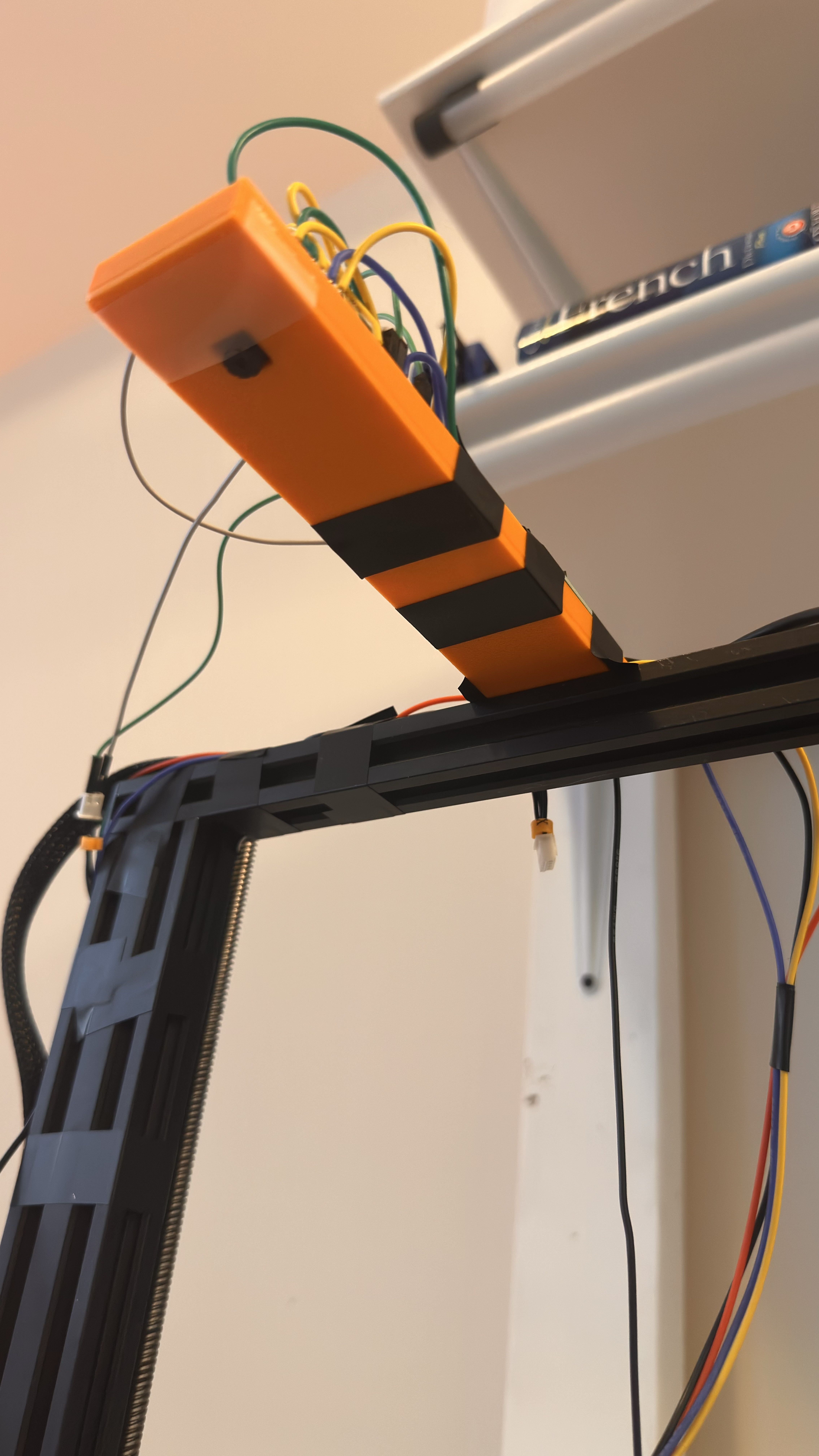
Replaced the print head with a custom-designed holder for an HX711 load cell, which is how the machine reads contact and compression force.
System Architecture
The ESP32-S3 Nova Cam sits at the center of the build, driving motion, reading force and limit switches, and passing frames to the PC over USB serial for vision processing.
How It Works
- 1
Homing
On startup, the machine homes all three axes against the limit switches to establish a known origin.
- 2
Imaging
The build plate moves to the camera position and the ESP32 captures an image.
- 3
Vision processing
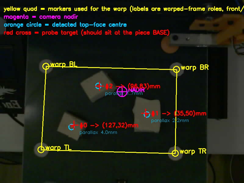
An OpenCV pipeline on the PC detects four fiducial markers that define the test area, counts the tofu pieces inside it, and computes each piece’s center coordinates.
- 4
Positioning
The ESP32 drives the X and Y axes to move the first sample under the probe.
- 5
Contact & height
The Z axis descends while the load cell is read continuously. The height at which force first rises marks contact, and gives the piece’s true height for free.
- 6
Compression curve
The probe presses a further 3 mm at a slow, controlled rate, streaming the force every 0.1 mm to capture the full force-vs-displacement curve.
- 7
Stiffness → class
The curve becomes an effective compressive modulus (kPa), a size-independent stiffness that grades the piece soft, firm, or extra firm.
- 8
Repeat
The machine indexes to the next piece and repeats until every sample in the test area has been measured.
Measuring Stiffness, Not Force
The machine grades each piece by its stiffness, an effective compressive modulus in kilopascals. Stiffness is a property of the tofu itself, so it stays the same whether a piece is cut thick or thin.
That independence is the point: tofu comes in all thicknesses, and a thinner slice compresses more under the same press than a thick one. Reading stiffness rather than raw push force lets the classifier compare pieces of any size on equal footing. The machine captures the full force-vs-compression curve on every press to compute it.
Stress
kPaHow hard the probe pushes, spread over its 426 mm² tip.
force ÷ probe area
Strain
ratioHow far the piece squished, relative to its own height.
compression ÷ height
Modulus
kPaStiffness, the same for a big or small cube of one tofu.
stress ÷ strain
Results
The machine reliably locates multiple samples in a single pass and classifies each one against calibrated stiffness (modulus) thresholds without operator input beyond loading the plate.
Future Improvements
Next, I plan to generate stress-strain curves from the load-cell data using MATLAB. After that I'll likely convert the machine into a plotter, since I don't have an ongoing need for a hardness analyzer. I built this to learn image recognition and to prove I could take a project like this from salvaged parts to a working system. It served both purposes.